
Access Control Planning
A Relay Contact Is Not Lock Power: Two Circuits That Are Easy to Treat as One
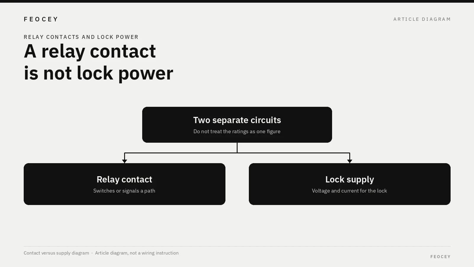
A relay contact can switch a lock circuit, but it does not supply the lock’s voltage or current. This article explains the two circuits, why their ratings are not interchangeable, and how to tell them apart on a drawing.
Before you choose
Key takeaways.
- A dry relay contact switches or signals a path; it does not create the lock’s voltage or current.
- A contact rating is not a power-supply instruction, and AC, DC and inductive figures must not be copied onto one another.
- This circuit distinction is not the same question as fail-safe versus fail-secure, which describes the lock’s state after its own power is removed.
A contact switches a path; it does not create the lock’s supply
A controller or a reader can have a relay, and a door can still have no usable lock power. The two facts are easy to merge because both appear in the same cabinet drawing. They are not the same circuit. This article explains what a relay contact does, what a lock power supply does, and how to read the two without treating one rating as a substitute for the other.
The subject is the electrical distinction, not a survey of which lock to buy. What a lock does after its own power is removed—fail-safe versus fail-secure—is a different question, and it only becomes meaningful once you know which circuit actually feeds the lock.
This is not a wiring recipe and does not tell anyone to jump terminals, work on a live circuit, or assume a default hookup. Disconnect power before work, and have a qualified installer check the supply, the lock load, and the project drawings.
A relay is an electrically operated switch. In access hardware the useful part is often the contact: two (or more) terminals that close or open when the relay is energized. When the contact is a dry contact, those terminals do not themselves provide a voltage. They only join or separate a path that already has, or is supposed to have, a source and a load.
The lock power circuit is that source and load. It has a voltage, a current, a location, and a protection arrangement. It may live in a power supply, a lock power controller, or another listed source specified for the opening. The relay contact may be inserted into that circuit, or it may only send a signal to equipment that then switches the lock. In either case the contact is not the supply.
Feocey’s four-door access control solution states the point in one sentence: a relay contact is not a statement of the power required by the lock. The installer still has to confirm the lock supply and the lock load. The same page also tells the installer to disconnect external power before wiring and to use only one of the controller’s own power inputs. That controller supply is the controller’s power. It is not automatically the lock’s power.
If a drawing shows “relay output” and nothing else, the lock still has no identified source.
Two ratings that are easy to swap
Because the contact and the supply are different, they carry different ratings, and those numbers are not interchangeable.
A contact rating describes what the contact is designed to switch—often a voltage, a current, and sometimes a load type. A supply rating describes what the source can deliver, or what the lock requires, at its own terminals. Using the contact rating as if it were a power-supply instruction is a category error. The corrected article Reader or controller: allocating the access decision already warns readers to separate reader power from lock power and to verify relay ratings. On the FCS525 reader, the same article notes a 12 V DC supply and a 30 V / 1 A relay contact rating, and it states that the relay rating is not an instruction to power the terminal at 30 V. The two numbers sit on one device because they describe two different things.
The kind of load matters as well as the number. Switching a resistive load and switching an inductive DC load, such as a lock coil or a magnetic lock, are not the same job. LifeSafety Power, in its application note on inductive loads, explains why. When a relay contact in the circuit of a simple magnetic load is opened, the current drops quickly, the magnetic field collapses, and the coil can briefly become a high-voltage source. That spike can cause arcing at the contacts and can disturb other devices on the wiring. See Inductive Loads in Life Safety Applications.
That note is a manufacturer’s explanation of the mechanism, not a Feocey wiring method and not a license to improvise a suppressor. Some locks include back-EMF protection; some do not, and internal protection can fail. If suppression is required, the method has to come from the lock, the power supply, or the approved project documents, and a qualified installer should apply it. This article does not prescribe a diode type or a jumper.
AC and DC ratings also must not be copied from one column to the other. A contact that can switch a given alternating current is not thereby shown to be suitable for the same current at DC, especially with an inductive load. Use the manufacturer’s DC and inductive figures when those are the conditions you have.
Three ways the two circuits can be arranged
The contact and the supply can meet in more than one way. The examples below are ways to read a drawing, not a menu of recommended hookups and not a claim that any one of them is the default for a particular controller.
**The contact is in the lock’s power path.** The supply feeds the lock, and the contact opens or closes that feed. You should still be able to point to the source, the load, and the contact as three labeled items. If any of the three is missing, the path is not yet described.
**The contact only signals another device.** The relay tells a lock power supply, a power controller, or another listed unit to switch the lock. The contact still does not generate the lock voltage. The current for the lock belongs to that other unit’s output, under that unit’s ratings.
**The contact is used only as a status or interlock signal.** It may report a granted output to another system without ever carrying the lock current. A lamp, an input, or a monitoring point can close and still leave the lock unpowered. On a drawing, you should be able to trace two loops: the coil or signal that operates the relay, and the path that actually energizes or releases the lock. If those loops collapse into one unlabeled line, the distinction has been lost. The same caution applies to a four-door controller. FCC4904, for example, provides relay outputs and door-circuit connections, and its product page states an external supply input of 12 V for the controller itself. That 12 V figure is a controller power fact. It does not, by itself, tell you the voltage, current, or source required by the lock at each door.
What to record so the two circuits stay visible
One short record is enough if it keeps the contact and the supply from being copied onto each other. Fill it from the manufacturer documents and the project drawing. Do not invent currents or “typical” values to make the row look complete.
If a cell cannot be filled, write “not stated” and leave the opening incomplete. A blank cell is not a rating.
| Item to record | Relay contact | Lock power supply | Why the two must stay separate |
|---|---|---|---|
| Function | Switches or signals a path | Provides the energy the lock requires | A closed contact is not a voltage source |
| Voltage and current | Contact rating, including AC or DC and load type if stated | Required lock voltage and current, and the source that will provide them | The contact rating is not a supply instruction |
| Location | The device that owns the contact | The supply or power-control unit for that opening | A cabinet can contain both without them being the same circuit |
| Protection or suppression | Follow the contact manufacturer’s limits | Follow the lock and supply documents; inductive DC loads may need a specified method | Do not improvise a jumper or an unstated diode |
| What a successful grant proves | That this output was commanded | Only that, if the supply and lock path are also complete | A grant can exist while the lock still has no usable power |
Common misunderstandings
These are reading errors, not a report of a particular cabinet.
- Treating “it has a relay” as “the lock is powered.”
- Using a contact rating, such as 30 V / 1 A, as the supply voltage or current for the reader or the lock.
- Copying an AC contact figure onto a DC inductive lock circuit.
- Assuming that the controller’s own 12 V input also feeds every lock.
- Borrowing one door’s lock supply design for a different lock type without reading that lock’s load.
- Adding an unofficial jumper or a guessed suppressor instead of following the lock and supply instructions.
- Treating this circuit question as if it already answered fail-safe or fail-secure behavior. Power-loss state is a property of the lock and of which circuit is removed, not a second name for the contact.
How to judge what you are looking at
Start with the terminals, not with the marketing name of the device.
Find the relay contact terminals and write only what the contact documentation claims to switch. Then find the lock’s supply terminals, or the output of the unit that is supposed to feed the lock, and write the voltage, current, and source from those documents. If you cannot point to both, you do not yet have two circuits. You have a label and a gap.
Next, ask whether the contact is intended to carry the lock current or only to signal another device. The answer has to come from the drawing and the manuals, not from a habit formed on a previous door. Then ask whether the stated contact rating covers the actual load type, including DC and inductance if that is what the lock presents.
Do that work with the power removed, using the project drawings, and have a qualified installer complete the check against the installation instructions. This article does not provide a live-testing sequence.
Limits, short answers, and the next distinction
This article does not publish a load table for any controller, does not specify a lock power product, and does not authorize a generic suppression circuit. LifeSafety Power’s explanation of back-EMF is cited only to show why an inductive DC load is not a simple switch rating. The actual method, if any, remains with the lock and supply documents.
**Does a relay output mean the lock has power?** No. The contact can only switch or signal a path. The lock still needs a defined supply and a complete load path.
**Can I use the contact rating as the lock’s power rating?** No. A contact rating, including the 30 V / 1 A example used for FCS525, is not an instruction to power a device at that voltage. Read the supply and the lock load separately.
**Is this the same question as fail-safe versus fail-secure?** No. This article is about which circuit is which. Fail-safe and fail-secure describe what the lock does when its power is removed. That question is worth asking only after the lock’s supply path has been identified.
**What should be written on the drawing before anyone applies power?** The contact, the lock supply, the load, and any manufacturer-specified protection, each with a source document. If one of those is missing, the two circuits have not yet been distinguished.
Source references
Feocey: Reader or controller: allocating the access decision ↗Feocey: Planning access control for an office building ↗Feocey four-door access control site survey checklist ↗Put the guide to work
Find the reference for your model.
Compare each device with your requirements. Confirm configuration and compatibility for the complete installation.
Discuss your project ↗