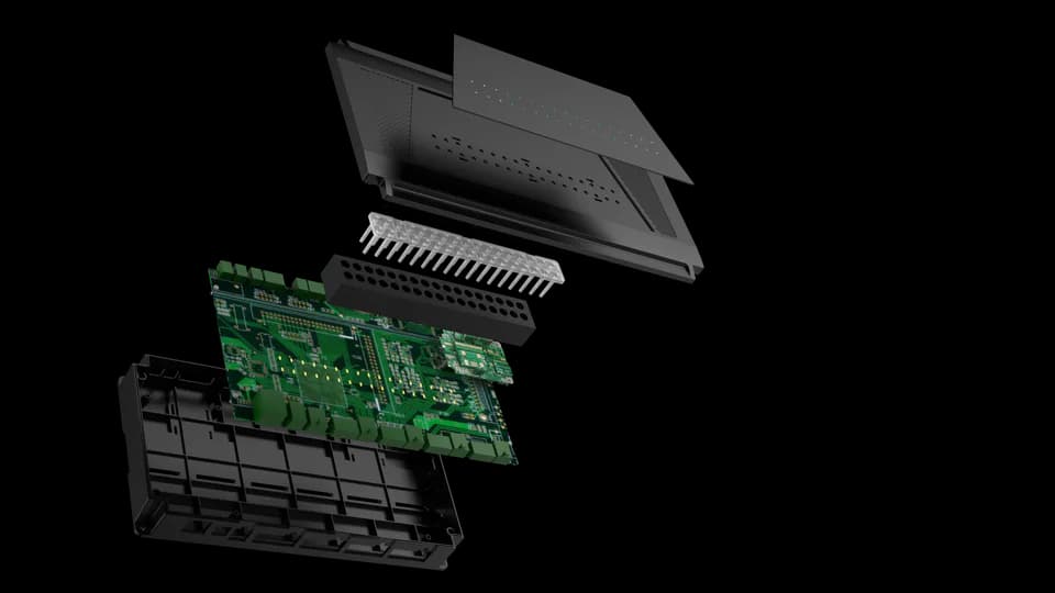
FCC4904
Central controller for four reader ports, lock relays, door contacts and exit inputs.
Product details ↗
Four-door access control solution
Bring readers, locks and exit controls together around the FCC4904. Shape each entrance around the people who use it, with a central point for door wiring and system integration.
The access journey
A clear operating sequence helps define the right hardware and software. Confirm reader compatibility and the permission logic for the selected configuration.
A reader captures the chosen credential at the entrance. Select QR, card or keypad hardware to fit the application.
The agreed controller and management setup checks the access request. Define permissions, schedules and offline behaviour with your integrator.
The configured relay and lock circuit provide the door action. Plan door contacts, exit buttons and emergency-release requirements together.
Explore the hardware
Start with the controller, then review the reader or keypad for each entrance. Reader options require a matching RS485 protocol and firmware. The separate keypad option uses Wiegand and is not presented as a direct FCC4904 reader connection.
Central controller for four reader ports, lock relays, door contacts and exit inputs.
Product details ↗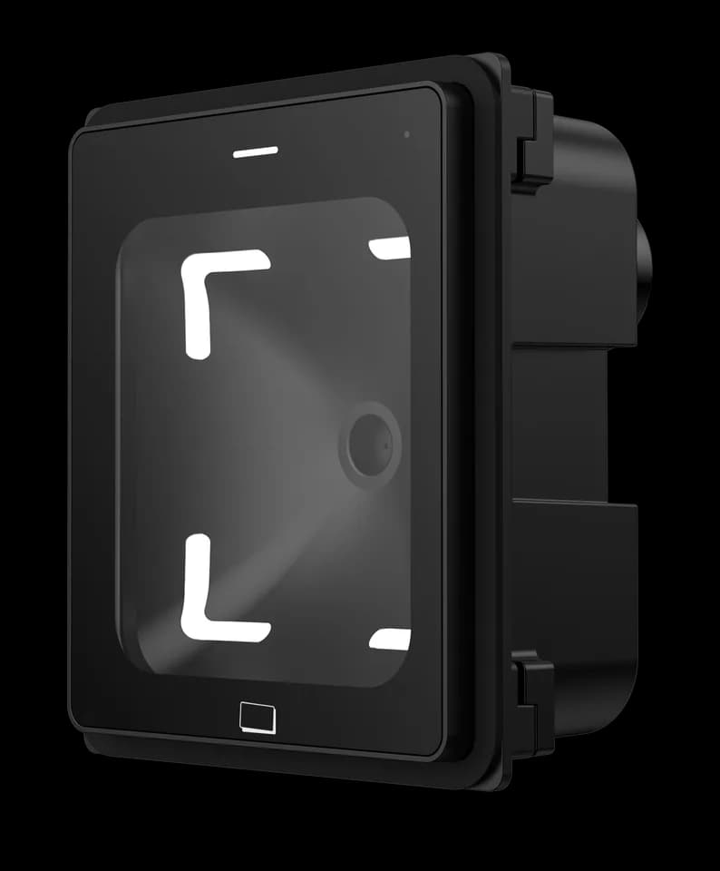
Compact QR reader option for the credential step at an entrance.
Product details ↗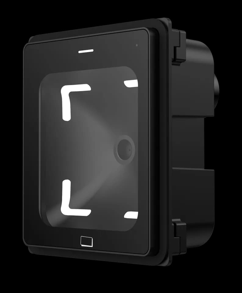
QR reader option to review against the mounting and host interface requirements.
Product details ↗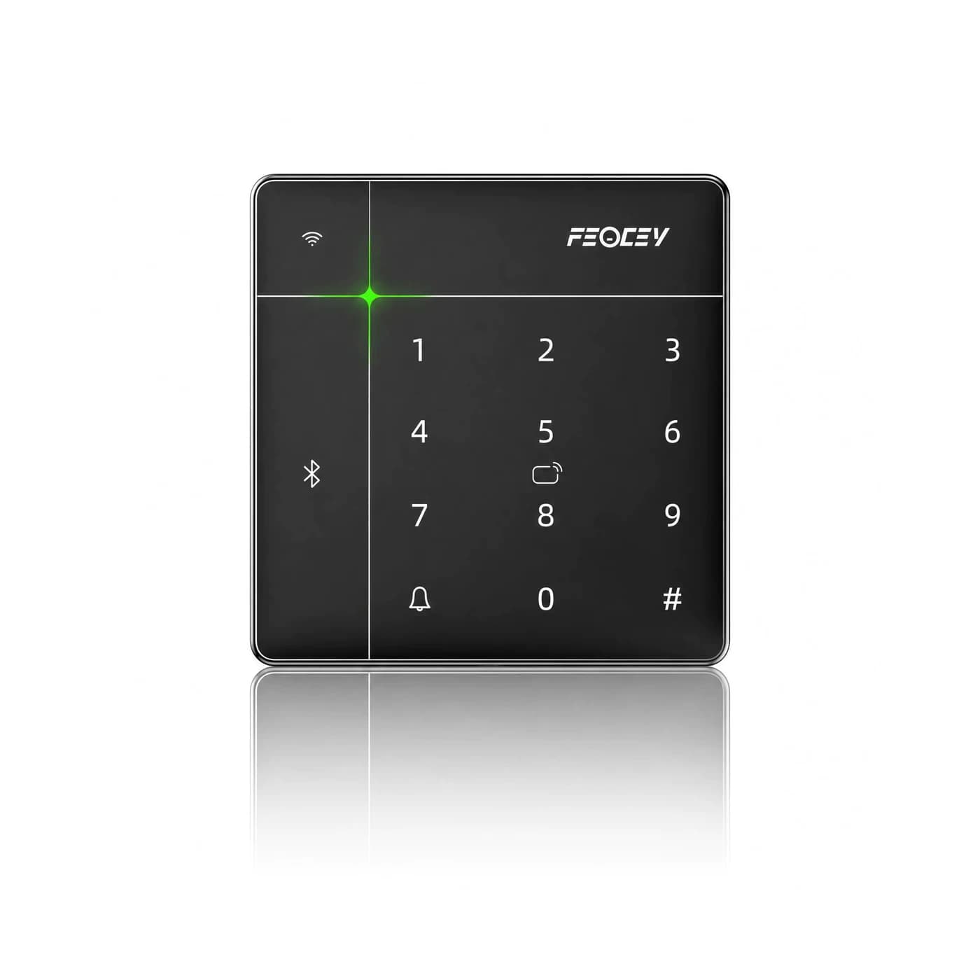
Separate keypad option with Wiegand output. FCC4904 reader ports are RS485; a direct pairing is not established.
Product details ↗Define each connection
Installation reference
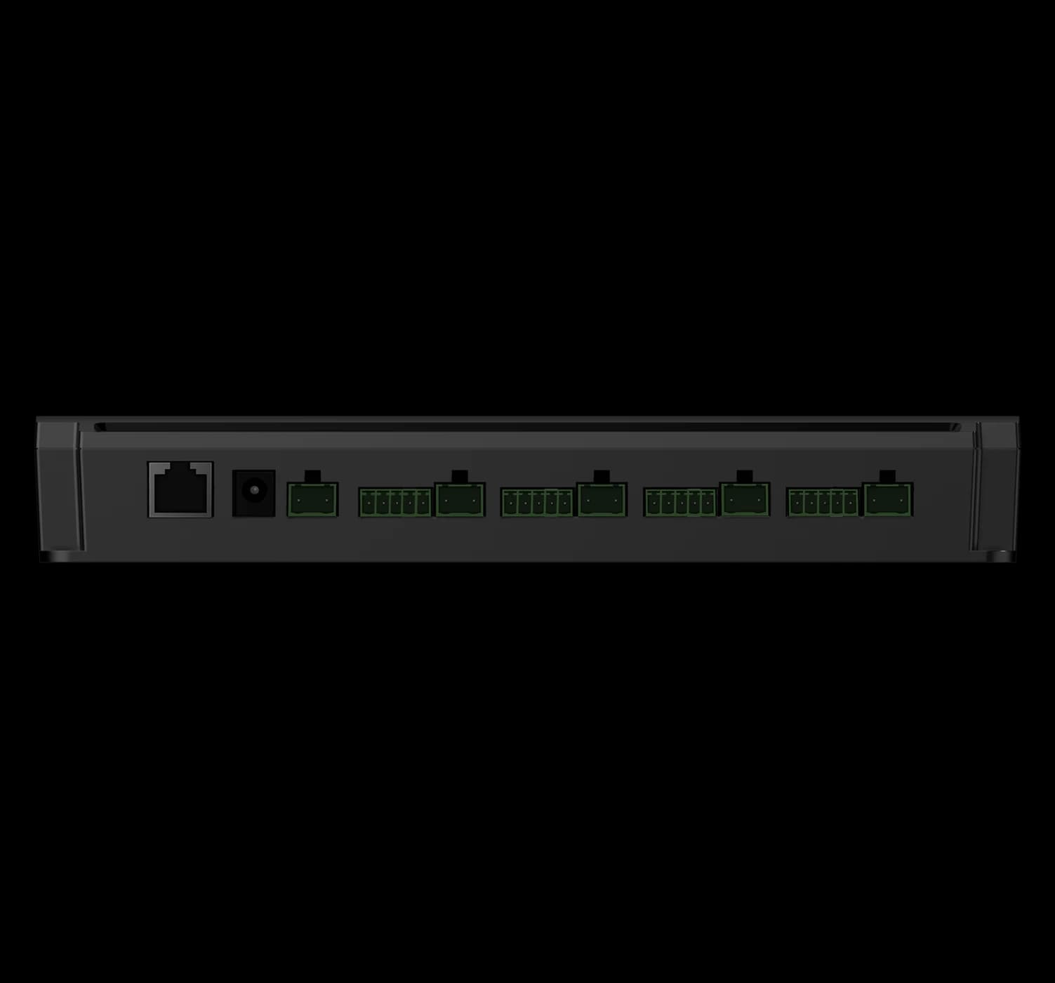
Disconnect external power before wiring. Have the installer confirm the supply, lock loads and fire-alarm integration. The following approved references show the controller terminals and wiring guidance.
Manual · English · PDF · 407 KB
Integration guide · English · PDF · 344 KB
Manual · English · PDF · 792 KB
Includes the FCC4901 / FCC4904 parameter table. Confirm enclosure dimensions and capacity with the team; the separate port and wiring references are also available.
Specification · English · PDF · 62 KB
For FCC4901, FCC4904
Shared table for single-door and four-door versions. Confirm variant, chassis dimensions and capacity before ordering or installation.
Test each reader and door separately: accepted and rejected credentials, exit-button operation, relay action and door-contact reporting. Agree the offline behaviour and have the installer verify the required emergency-release arrangement. Do not treat a successful card read as proof that the complete door circuit is correct.
Check the reader interface, protocol and firmware against the controller configuration. An interface name alone does not establish compatibility. Send the selected model list with your installation requirements.
Share the door count, reader models, lock type and load, exit controls, network plan and management software. Include the applicable fire-alarm and emergency-release requirements for the site.
Tell us how people enter, how they leave and which system manages permissions. We will help confirm the equipment and integration scope.
Allow Google Analytics to help us understand traffic sources, page visits, submitted inquiries, document clicks, email-link clicks and visits to Alibaba or WhatsApp. We do not send your name, email or inquiry message to Analytics.
Analytics stays off until you allow it. Your choice does not affect inquiries or videos you choose to play. You can change it here at any time.
Current choice: not selected.
Read the website privacy notice