QR Readers & Terminals

FC8135

Embedded QR and card reader

Build QR reading into your equipment.

An embedded QR reader for gates, kiosks and self-service equipment. Read phone or paper codes and select the interface and optional card module for your host system.

  • Embedded installation
  • Phone & paper codes
  • Card-reading options
Installation
EmbeddedFor an equipment panel
Body size
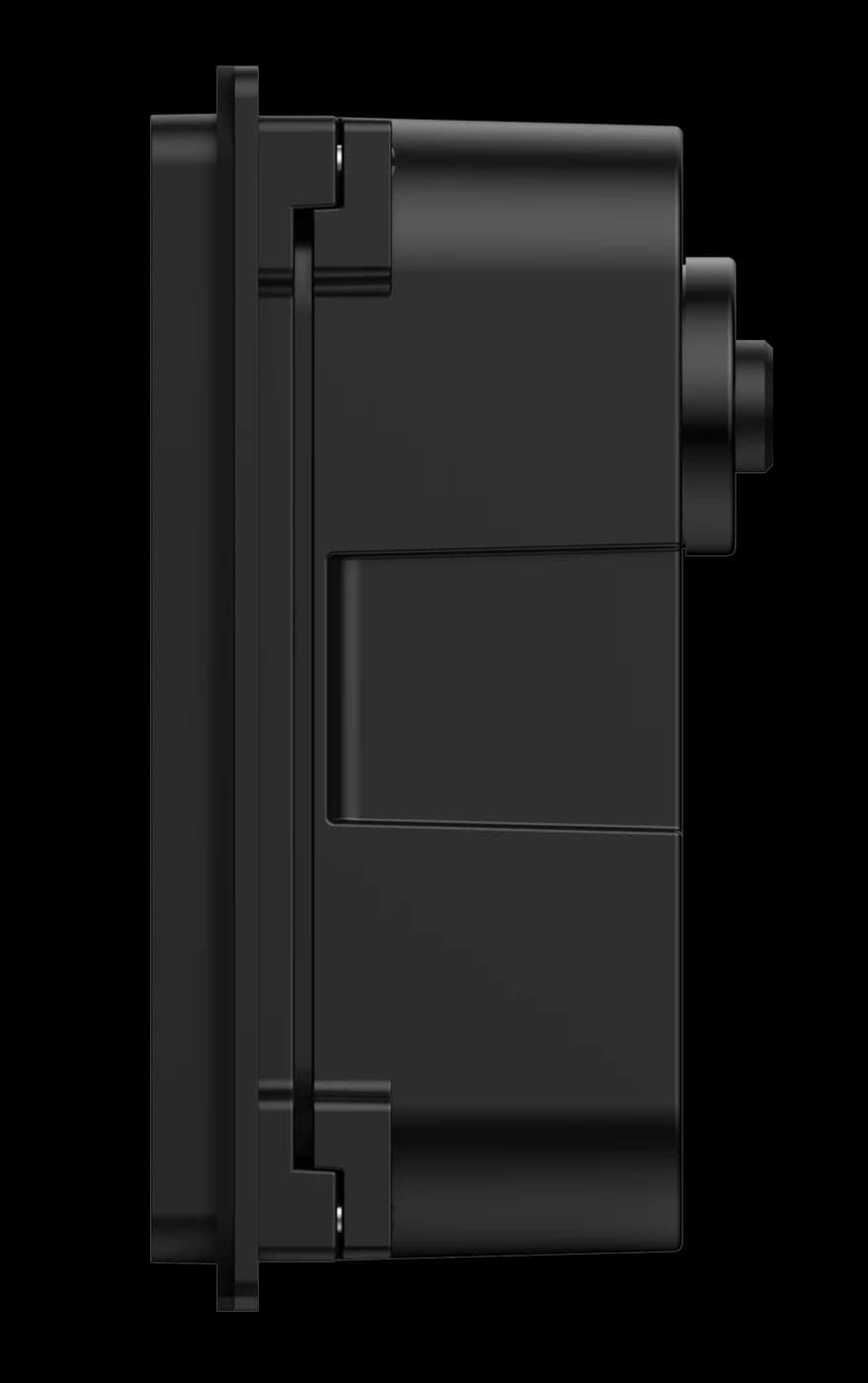
75 × 65 mm35.10 mm body depth
Presentation
Phone + paperSelect optional card capability

Inside FC8135

Build the scan point into your equipment.

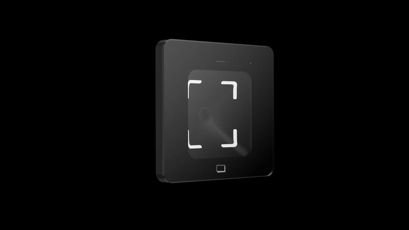
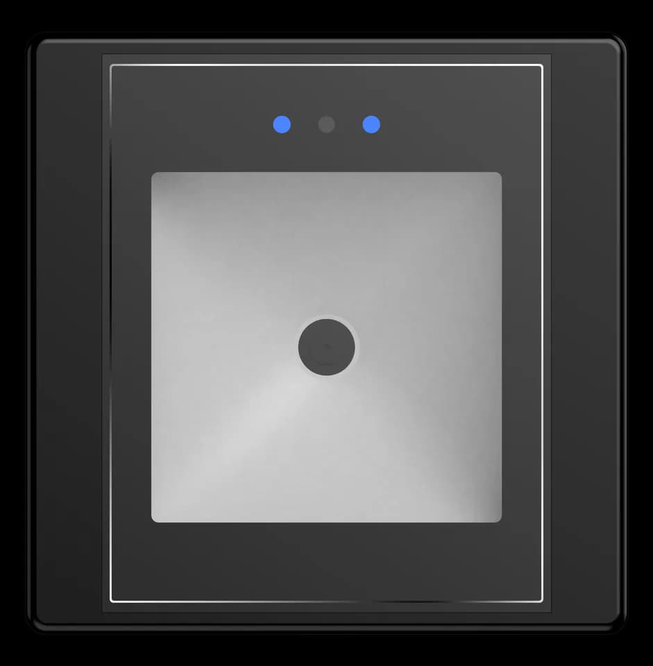
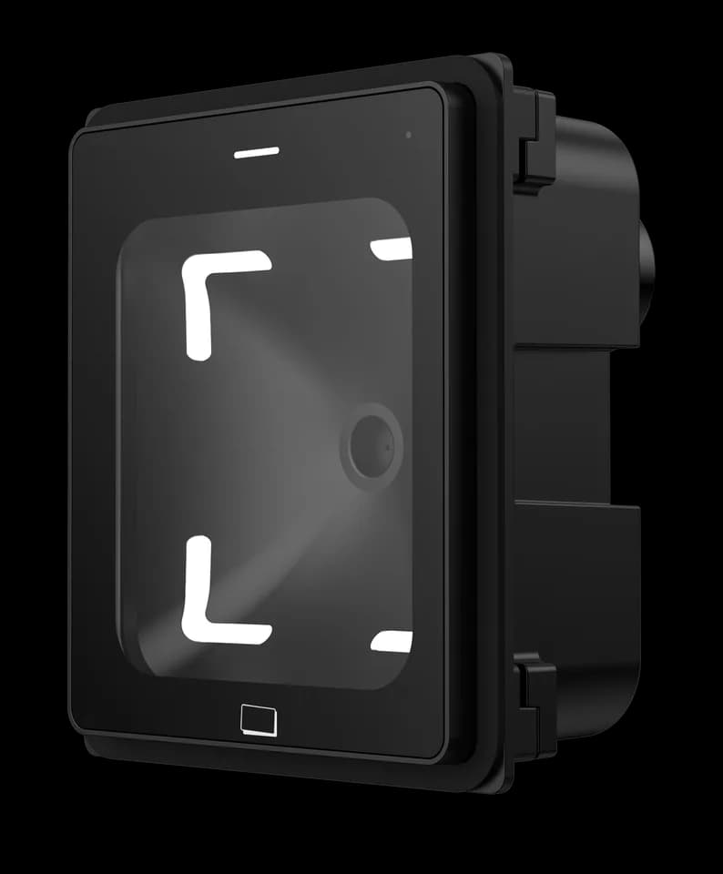
FC8135 is an embedded reader for a gate, kiosk or self-service enclosure. The front presents the reading window; the mounting points and connections sit within the equipment. Design the panel opening and rear clearance together, then choose the interface that your host can receive.

Plan the installation
FC8135 side view showing body depth and mounting tabs
FC8135 · profile and mounting tabs

Choose around your project

The details that
make it fit.

01

Start with the panel

Use the dimension drawing to check the opening, mounting holes and body clearance. The 75 × 65 mm enclosure dimensions are not a panel-cutout template.

02

Select the output version

Choose RS485, RS232, TTL, Wiegand or Ethernet to suit the host. Confirm the data format and supplied harness as well as the interface name.

03

Keep the interaction clear

Allow room to present a phone or printed pass. Indicators and a buzzer provide reading feedback; the host application determines the next action.

From credential to action

How the parts
work together.

Embedded describes the installation. It does not remove the need for a host application, a matching interface and an appropriate power supply.

  1. 01

    Scan at the panel

    The user presents a code at the equipment’s reading window.

  2. 02

    Send to the host

    The selected interface delivers the decoded data to the equipment controller or application.

  3. 03

    Continue the service

    The host validates the credential and decides whether to admit the user or continue the equipment workflow.

Example workflow · confirm the configuration and wiring for the supplied equipment.

Technical details

A closer look.

Options vary by configuration. Use these details to plan your evaluation.

FC8135 specifications
MountingEmbedded installation
Dimensions75 × 65 × 35.10 mm
Code sourcesPhone-screen and printed QR codes
Output optionsRS485, RS232, TTL, Wiegand and Ethernet; select the required version
FeedbackRed, green and white indicators with buzzer
Power inputSerial / Wiegand / TTL versions: 5–15 V DC; Ethernet version: 12–24 V DC

Installation & connections

Plan the fit.

  1. Use the dimension drawing for the panel opening and mounting holes. Allow for the 35.10 mm body depth, connector space and cable bends behind the panel.
  2. Match the supplied interface and harness to the host. Serial, Wiegand and TTL versions use 5–15 V DC; Ethernet uses 12–24 V DC. Connect with the power off.
  3. Protect the reading window from scratches and avoid direct sunlight or strong light. Check metal around the reading area when a card module is selected.
  4. Before closing the enclosure, test representative phone and paper codes, host data reception and the equipment’s allowed and denied workflows.

Product resources

Manuals & drawings.

Documents for FC8135 →
  • FC8135 user manual

    Manual · English · PDF · 615 KB

    The source manual uses the Q350 hardware designation.

    Download PDF

A few things worth knowing.

Can the same configuration tool be used for every reader?

Do not assume so. Reader firmware and access-control firmware can use different tools, configuration codes or platform commands. Share the overseas model, firmware and intended operating mode so the matching method can be checked before changing settings.

What should I check if serial output is missing or unreadable?

Match the baud rate, data format and electrical interface on both sides, then inspect the cable and any serial-to-USB adapter. Also confirm whether the reader is sending raw content or a framed protocol message before treating additional bytes as corrupted data.

What should we check when a reader does not react to a code?

First confirm that the reader has started normally and that the code is complete, correctly generated and presented within the usable reading area. For codes shown on a phone, raise the screen brightness and remove glare; if known-good codes still produce no response, record the indicator and buzzer behavior for support.

Your next step

Let’s put FC8135
in your project.

Tell us where it will be used, how it should connect and the quantity you need.

Discuss your project