
Installation planning
Can a Wiegand reader connect to an RS485 controller?
Check reader output, controller input, credential format and door-control responsibility before combining access devices. A worked example using FCS525 and FCC4904 documentation.
Before connecting the devices
A reader and a controller should be selected as a documented combination. The fact that both are described as access-control products does not establish that their reader connections, credential formats or software will work together. Start with the exact supplied models and their connection references before deciding how to wire the entrance.
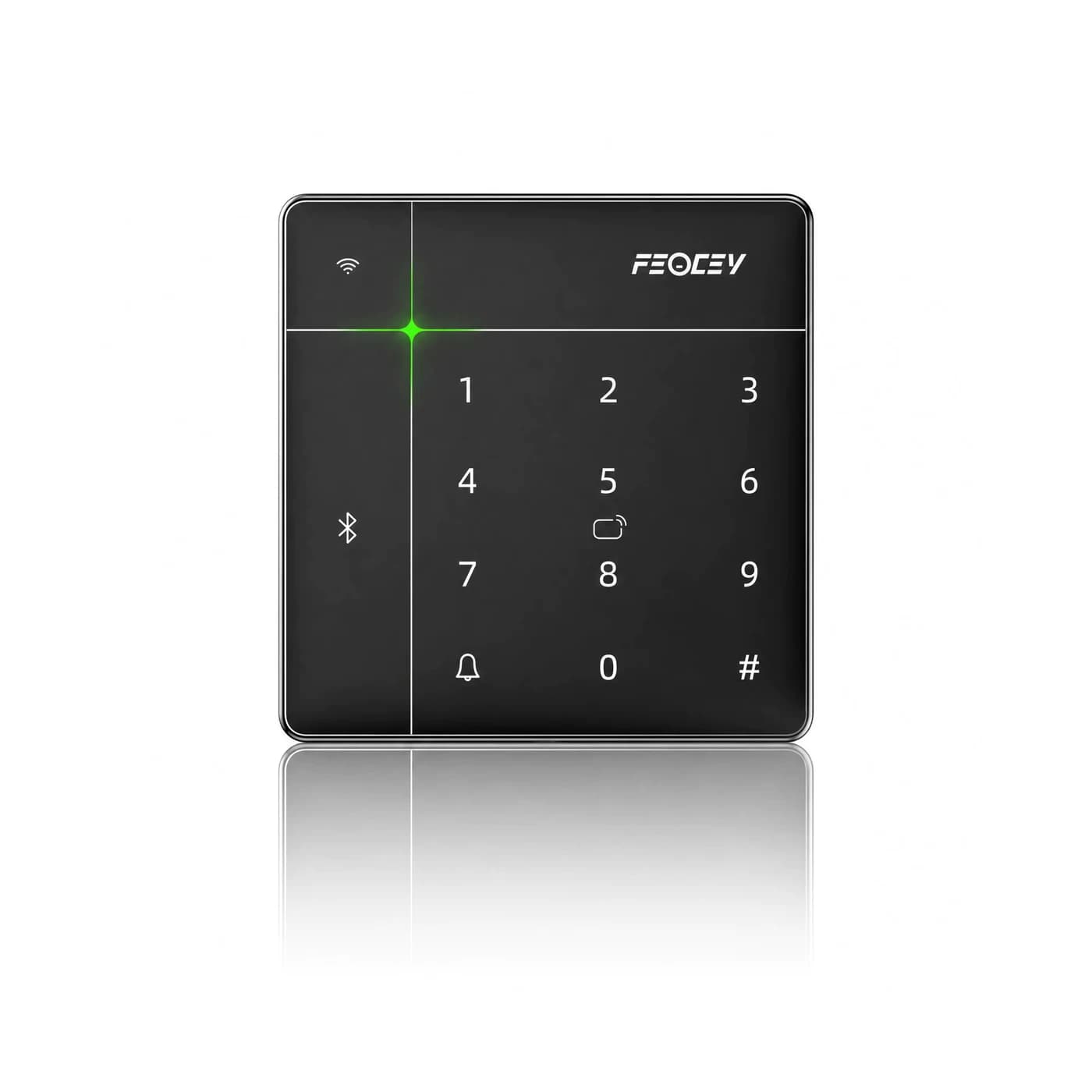
The FCS525 and FCC4904 manuals provide a useful example. The FCS525 manual identifies Wiegand 26/34 output. The FCC4904 port description identifies 485A and 485B at its reader connection. These references describe different interfaces; they do not establish a direct pairing between these two products. Have the complete integration path confirmed before ordering them as a set. [1][2]
1. Read the output and the receiving input together
For the proposed reader, record the interface name, terminal labels and supported data format. For the controller, find the corresponding receiving connection in its own manual. Compare the two references side by side instead of relying on a product-family name or the number of terminals.
FCS525 documents Wiegand 26/34 output at VG-D0 and VG-D1. FCC4904 identifies A and B terminals as 485A and 485B in the reader-port table. A diagram for one product cannot be reused as a connection diagram for the other. The published documents used here do not provide a conversion arrangement or an approved compatibility statement. [1][2]
Ask the supplier to identify the accepted reader, controller version, firmware and wiring reference for the proposed system. If an additional interface device is proposed, request documentation for that complete arrangement and include it in the pilot. This guide does not recommend an unspecified converter.
2. Decide which component makes the access decision
Reading a credential and deciding whether a person may enter are separate steps in an access workflow. Write down where credentials are enrolled, where permission rules are maintained and which component requests the door action for the selected operating mode.
A reader response alone is not a complete acceptance result. During the pilot, compare what appears at the entrance with the permission decision and the intended physical door action. Include an allowed credential, a denied credential and a credential whose permission has changed. Use the actual application and supplied firmware; do not infer behavior from another model's screen or demonstration.
For the four-door design, keep a per-door record of the assigned reader, lock circuit and relevant input. The FCC4904 port documentation distinguishes reader connections from lock terminals, exit-button inputs and door-status inputs. Those responsibilities should remain clear in the installation drawing. [2]
3. Check the power and relay circuit separately
Interface compatibility does not complete the electrical plan. Record the device supply, lock supply, connector pinout and relay load for the supplied equipment. Have the installer review the complete circuit against the manufacturer’s references.
For FCS525, the manual describes a 12 V DC supply and lists a 30 V / 1 A relay contact rating. The relay rating is not an instruction to power the terminal at 30 V. Keep supply and contact-rating information in separate fields of the installation checklist. This article is a planning aid, not a replacement for the product wiring instructions. [1]
4. Accept the complete workflow before repeating it
Start with one representative entrance. Verify normal access, denial, exit operation, permission changes and the agreed response to a network interruption. Record what each component does and how the system returns to its expected state. Confirm any required offline behavior explicitly rather than assuming it is shared by every reader or controller.
The accepted record should name the hardware, firmware, application, wiring reference and tests performed. If a component changes, review the affected part of the arrangement before repeating the installation across more doors. A successful test on one configuration should not be presented as universal compatibility for a product family.
Information to send with your inquiry
For the documented product details, start with FCS525 and the four-door access-control planning page. Contact Feocey with both model references so the complete arrangement can be reviewed.
- Exact reader and controller models, with hardware or firmware versions where available.
- Reader output and controller input references, including the relevant manual pages.
- Credential type, management application and required permission workflow.
- Door count, lock supply and load, exit arrangements and installation drawings.
- Required normal, rejected and recovery outcomes for the pilot.
Source references
FCS525 Product Manual, pp. 6 and 9 ↗FCC4904 Port Description, pp. 1–2 ↗Put the guide to work
Find the reference for your model.
Compare each device with your requirements. Confirm configuration and compatibility for the complete installation.
FCS525 →
Access keypad and IC card reader
Ask about FCS525 ↗FCC4904 →
Access controller
Ask about FCC4904 ↗