Turnstiles & Gates

FC-TFTZQ

Bridge tripod turnstile

Bridge tripod turnstile.

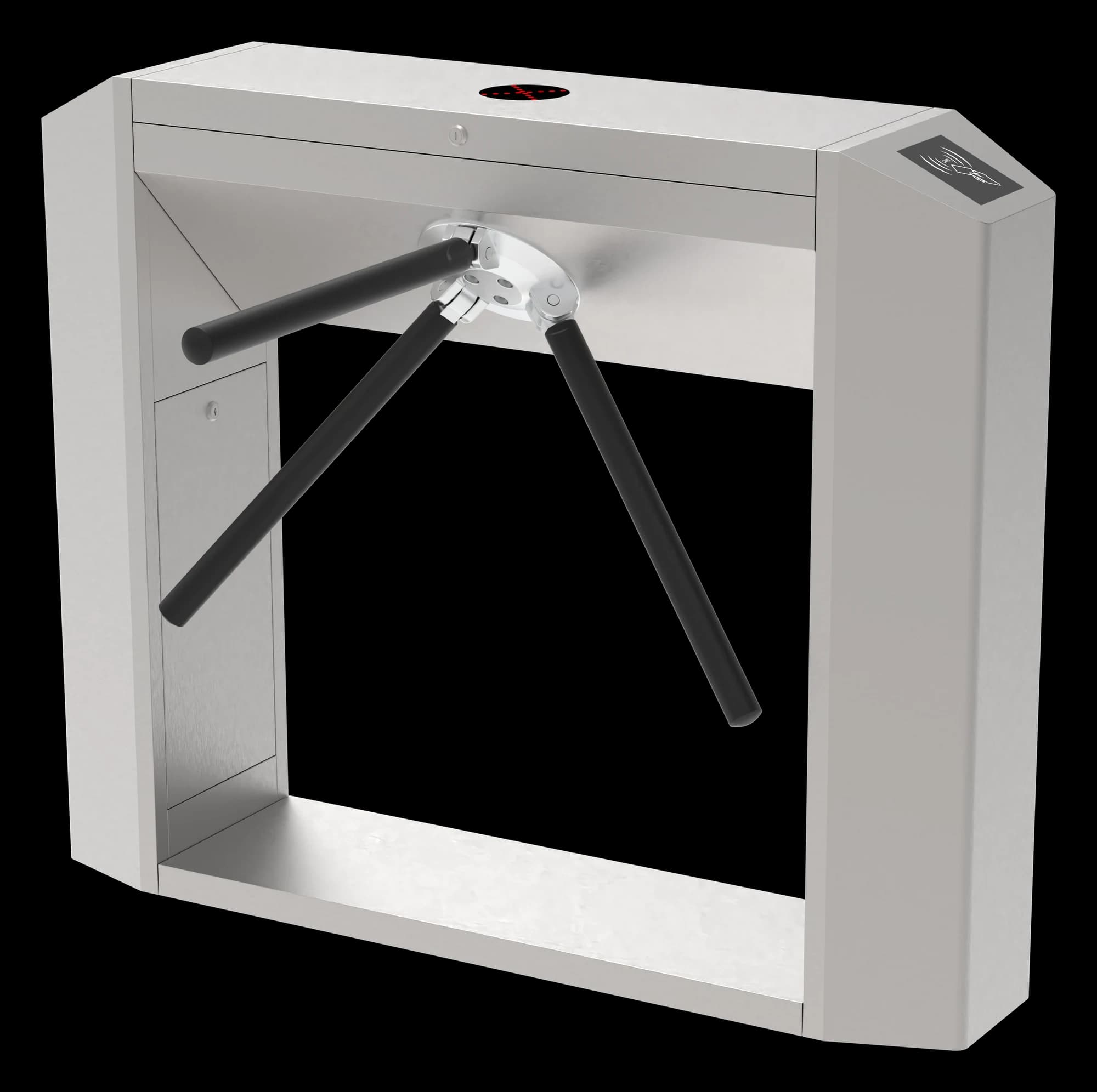
A bridge tripod with direction indicators and a choice of mechanism configuration. Review the selected controller and passage arrangement for the project.

  • Bridge cabinet
  • Direction indicators
  • Mechanism configuration options

Choose your configuration

Standard mechanism configuration. Confirm the supplied assembly and the complete installation drawing.

Your choice is included in the enquiry. Our team will confirm the supplied configuration and layout.

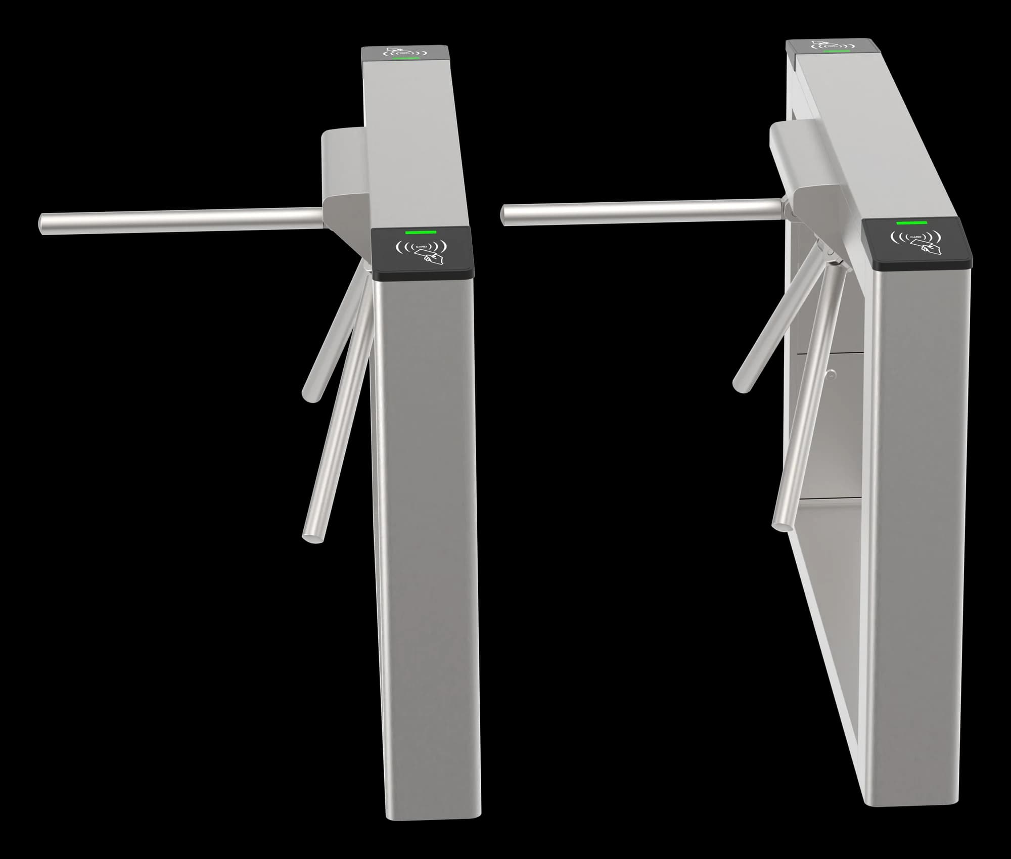
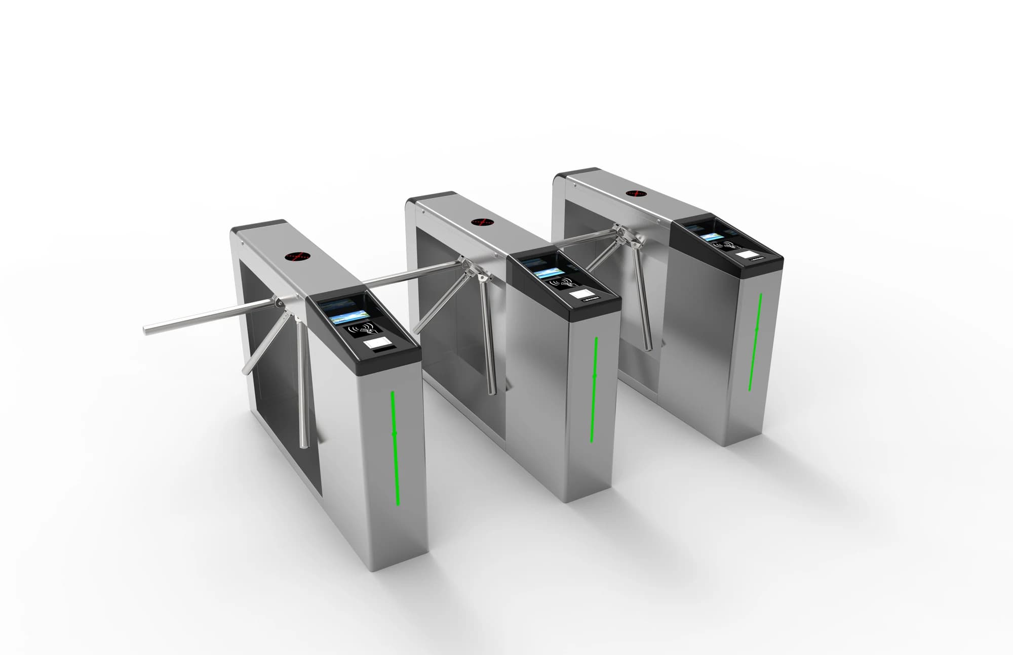
FC-TFTZQ slim rectangular tripod cabinets in an oblique arrangement
FC-TFTZQ · Cabinet arrangement illustration. Confirm the mechanism configuration and required cabinet quantities; pictured readers are not standard equipment.

Bridge tripod turnstile.
Plan your entrance.

A bridge tripod with direction indicators and a choice of mechanism configuration. Review the selected controller and passage arrangement for the project.

Structure
Tripod turnstiles
Configuration
Select the mechanism
Installation
Confirm the order drawing

Product views show possible cabinet and lane arrangements. Readers and terminals are selected separately; final quantities and dimensions follow the confirmed order drawing.

Technical specifications.

FC-TFTZQ · Standard

Parameters describe the listed model configuration. Confirm the selected mechanism, final cabinet and lane dimensions, controller and order drawing. Throughput varies with access checks and passage conditions.

FC-TFTZQ specifications
ConfigurationStandard
StructureBridge tripod turnstile
Cabinet dimensions1400 × 280 × 980 mm
Passage width550 mm
Cabinet / frame material304 brushed stainless-steel cabinet; SUS201 arms
Standard mechanismSemi-automatic mechanism with hydraulic buffering
More specifications
FC-TFTZQ additional specifications
Specified electrical supply24 V / 50 W; confirm the supply stage and wiring
CommunicationRS485; confirm the controller protocol
IndicatorDynamic direction / status lighting
FC-TFTZQ slim rectangular tripod cabinets in an oblique arrangement
FC-TFTZQ · Cabinet arrangement illustration. Confirm the mechanism configuration and required cabinet quantities; pictured readers are not standard equipment.

Match the gate
to the entrance.

Workplaces, business parks and supervised access checkpoints. Plan the queue, cabinet positions and the separate accessible passage around the entrance.

Product views show possible cabinet and lane arrangements. Readers and terminals are selected separately; final quantities and dimensions follow the confirmed order drawing.

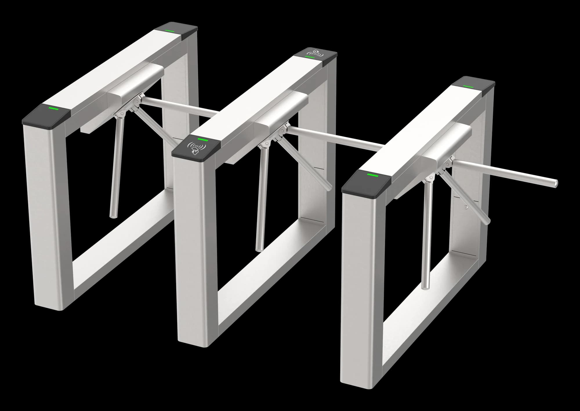
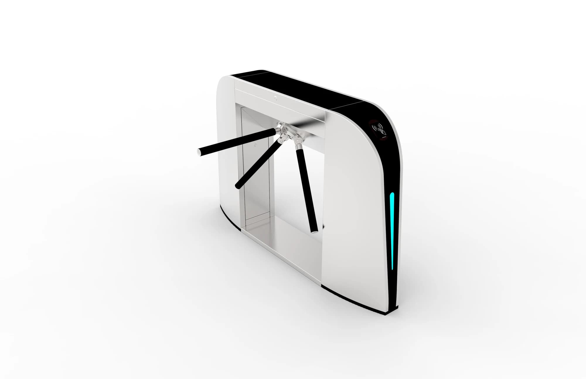
FC-TFTZQ two slim tripod cabinets viewed from the passage entrance
FC-TFTZQ · Cabinet arrangement illustration. Confirm the mechanism configuration and required cabinet quantities; pictured readers are not standard equipment.

Plan the credential check.
Confirm the connection.

Choose the reader and access controller for the required credential workflow, then confirm the gate input, signal timing, wiring and controller protocol. Commission the passage sequence, sensor response and emergency behaviour with the actual configuration.

Reader compatibility depends on the selected controller and signals. Credential readers, software and gate hardware are specified separately.

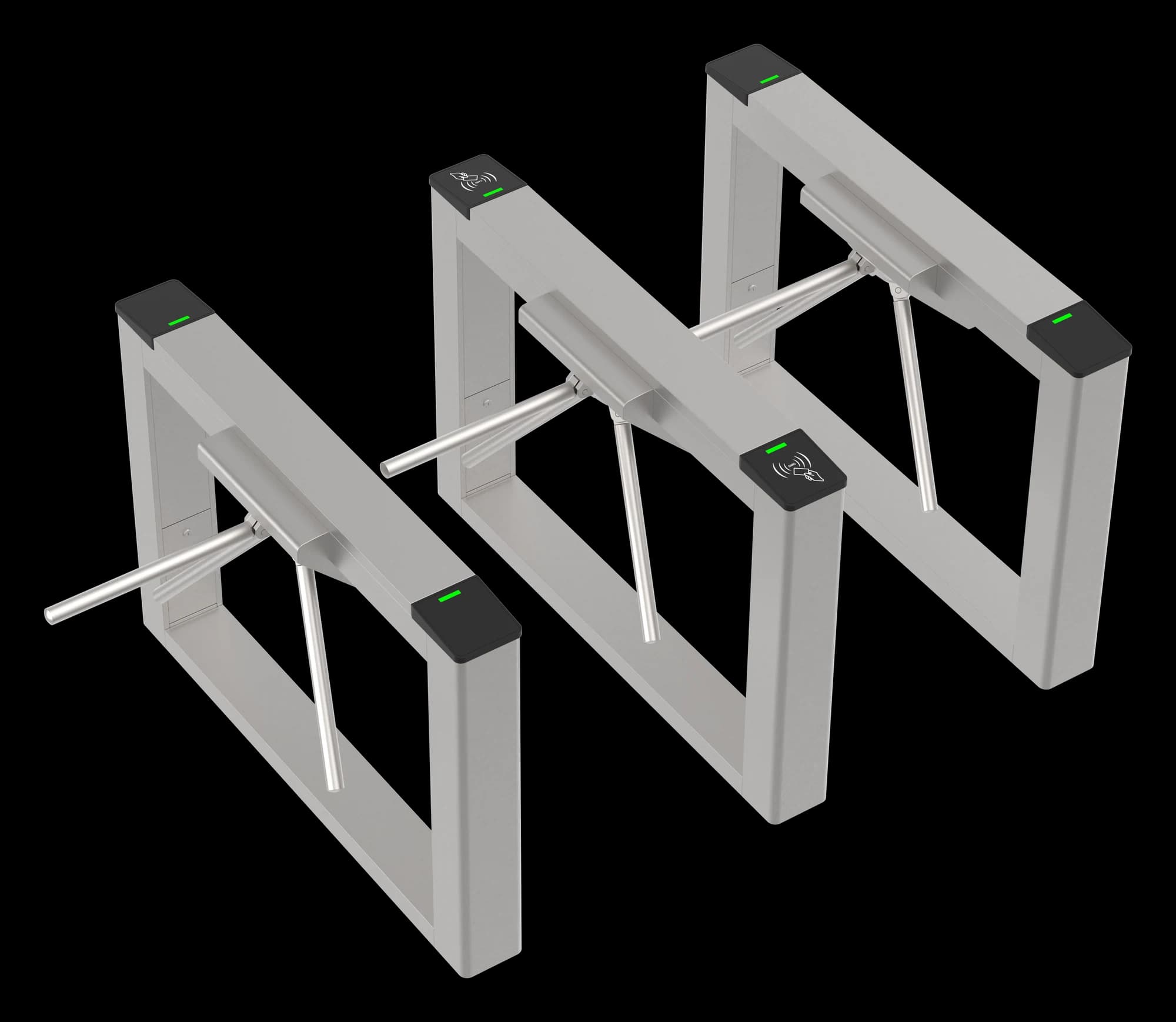
FC-TFTZQ slim tripod cabinets and rotating arms viewed from above
FC-TFTZQ · Cabinet arrangement illustration. Confirm the mechanism configuration and required cabinet quantities; pictured readers are not standard equipment.

Review the cabinet.
Plan the layout.

Use the additional supplied view to review the appearance and cabinet arrangement. Match the selected mechanism and complete entrance footprint to the approved order drawing.

Product views show possible cabinet and lane arrangements. Readers and terminals are selected separately; final quantities and dimensions follow the confirmed order drawing.

FC-TFTZQ slim tripod cabinets and rotating arms viewed from above
FC-TFTZQ · Cabinet arrangement illustration. Confirm the mechanism configuration and required cabinet quantities; pictured readers are not standard equipment.

Measure the entrance.
Confirm the drawing.

Provide the entrance width, lane count, user requirements, floor construction, cable routes and service clearance. Obtain the approved model and configuration drawing before preparing fixing holes or wiring. Check the separate accessible route and the project’s emergency requirements.

  • Confirm the selected mechanism’s cabinet dimensions and passage width.
  • Review its electrical supply, controller and required signals.
  • Confirm cabinet count, reader mounting, cable routes and service clearance.
Request documents for FC-TFTZQ

The product view is not a drilling template or a certified site plan. A matching operating manual and installation drawing must be requested for the supplied configuration.

Product resources.

Manuals and integration support for FC-TFTZQ.

Documents for FC-TFTZQ →

Request the manual, dimension drawing and integration reference for your FC-TFTZQ configuration.

Request documents for FC-TFTZQ

Your questions, answered.

How do we choose a gate structure?

Start with the passage workflow, available space and users. Swing gates use swinging barrier leaves; flap gates retract their barriers; tripod turnstiles use a three-arm mechanism; full-height turnstiles use a rotating barrier; AB gates coordinate two sequential stages. Review the lane layout, supervision, accessible route and emergency behaviour with the project team.

Does a single-mechanism cabinet mean a complete single lane?

For compatible swing and flap systems, a single-mechanism cabinet controls one side of a lane. Two matching outer cabinets form one lane; adding a compatible double-mechanism cabinet between them can form two lanes. Single and double mechanisms describe cabinet configurations, not complete lane quantities. Tripod, full-height and AB gates use their own arrangements. Confirm the final quantities and footprint on the project drawing.

Is cabinet size the same as clear passage width?

No. Cabinet size, clear passage width and the complete installed footprint describe different measurements. Confirm the cabinet arrangement, arm or barrier movement, accessible route, fixing pattern and service clearance using the approved project drawing.

Are the pictured readers and face terminals included?

The pictures illustrate possible access configurations. Confirm the gate, readers, terminals, controllers, software and quantities in the order. Match the credential output, gate input, control protocol and power arrangement before integration.